This blog post documents my first go at installing a DCC Decoder chip into a Hornby Class 86 Locomotive.
Having recently got my Hornby train set out I happened to accidentally find myself on eBay bidding for some trains Hornby originally released back in the early 2000s. My mission was to collect the Hornby ‘East Anglia’ franchise of locomotives and coaches. When living in Norfolk I regularly travelled on ‘Anglia Railways’ through various differently branded franchises on the line to London so this is where building my collection begins.
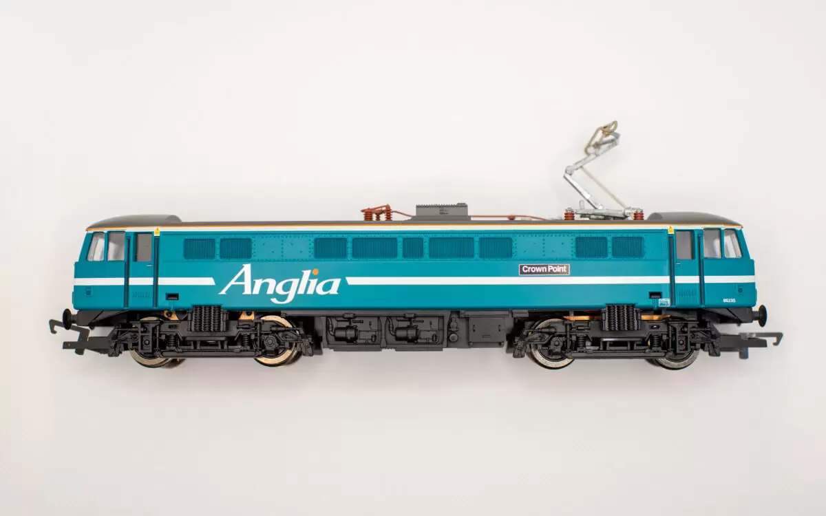
I found this fantastic example of the Hornby R2160 Class 86 ‘Crown Point’ locomotive and snapped it up. It’s in mint condition and runs brilliantly. So here we go! Time to install a DCC Decoder.
Upgrading to DCC
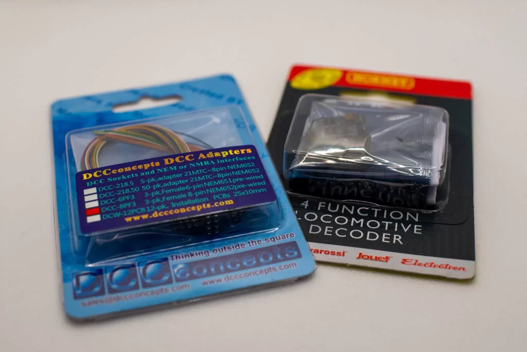
First up the decoder I chose was the R8249 Hornby Locomotive Decoder. I know there are others on the market but my weird logic was Hornby train = Hornby decoder. Perhaps as I upgrade more of my old locomotives in time I’ll try some of the others.
I’m also using a DCC Concepts 8 pin adapter socket so I’m not hard wiring the DCC Decoder into the locomotive. Gives me options to change it out in the future without having to get the soldering iron out.
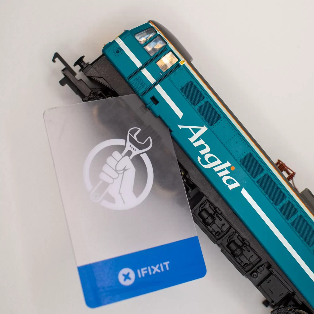
Step 1: Remove the body
This is pretty straight forward on the Hornby Class 86. Theres 4 catches on the chassis that need to be released. I did this easily enough by pushing a plastic card between the body and the chassis near all 4 corners.
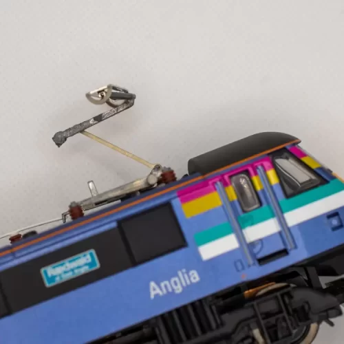
Step 2: Disconnect the Pantograph
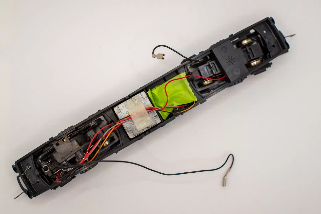
The Pantograph on the top of this locomotive is capable of being the power source when running on overhead power lines. Not something Hornby does anymore. A switch on the roof moves the loco between track power and pantograph and this switch sits in series on the black wire. It’s connected with a couple of spade connecters which simply pull off from the inside roof of the body.
You’ll see I opted to use a strip of masking tape to hold the pantograph down – these are exceptionally rare as a spare part and very expensive if you manage to find one, so I taped it down to prevent accidental damage.
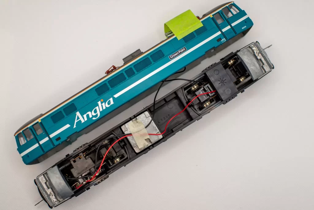
Hornby really doesn?t make models like they used to. There are three lead weights in here. At each end they form the cab interior with a dashboard and controls, and there’s an extra one for ballast in the middle.
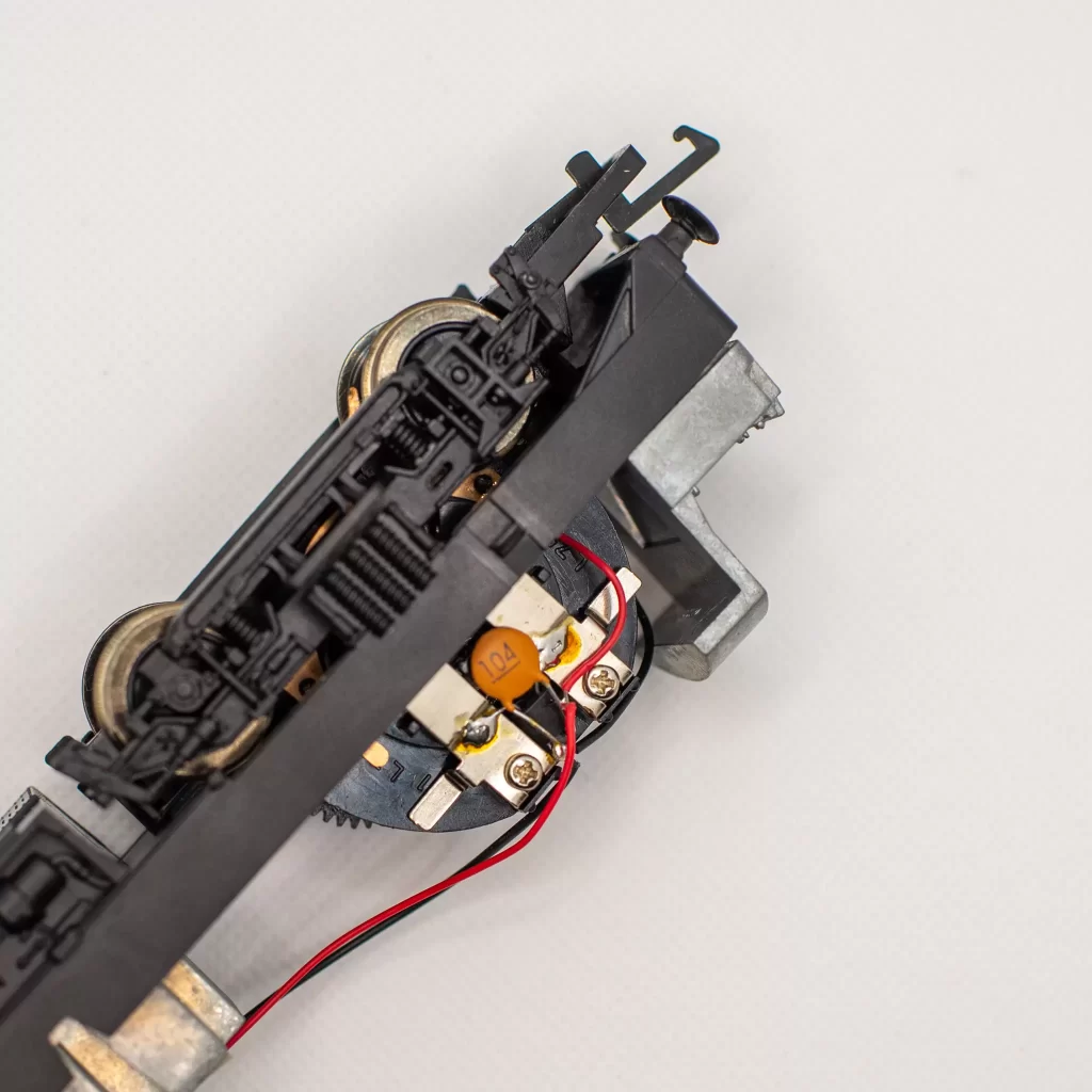
Step 3: Remove the capacitor
Time for the soldering iron. The capacitor is not needed for DCC operation so it’s going. The Capacitor legs are soldered across the connections of the motor.
First I desoldered the red and black wires to remove them from the capacitor legs, then the capacitor itself from the motor.
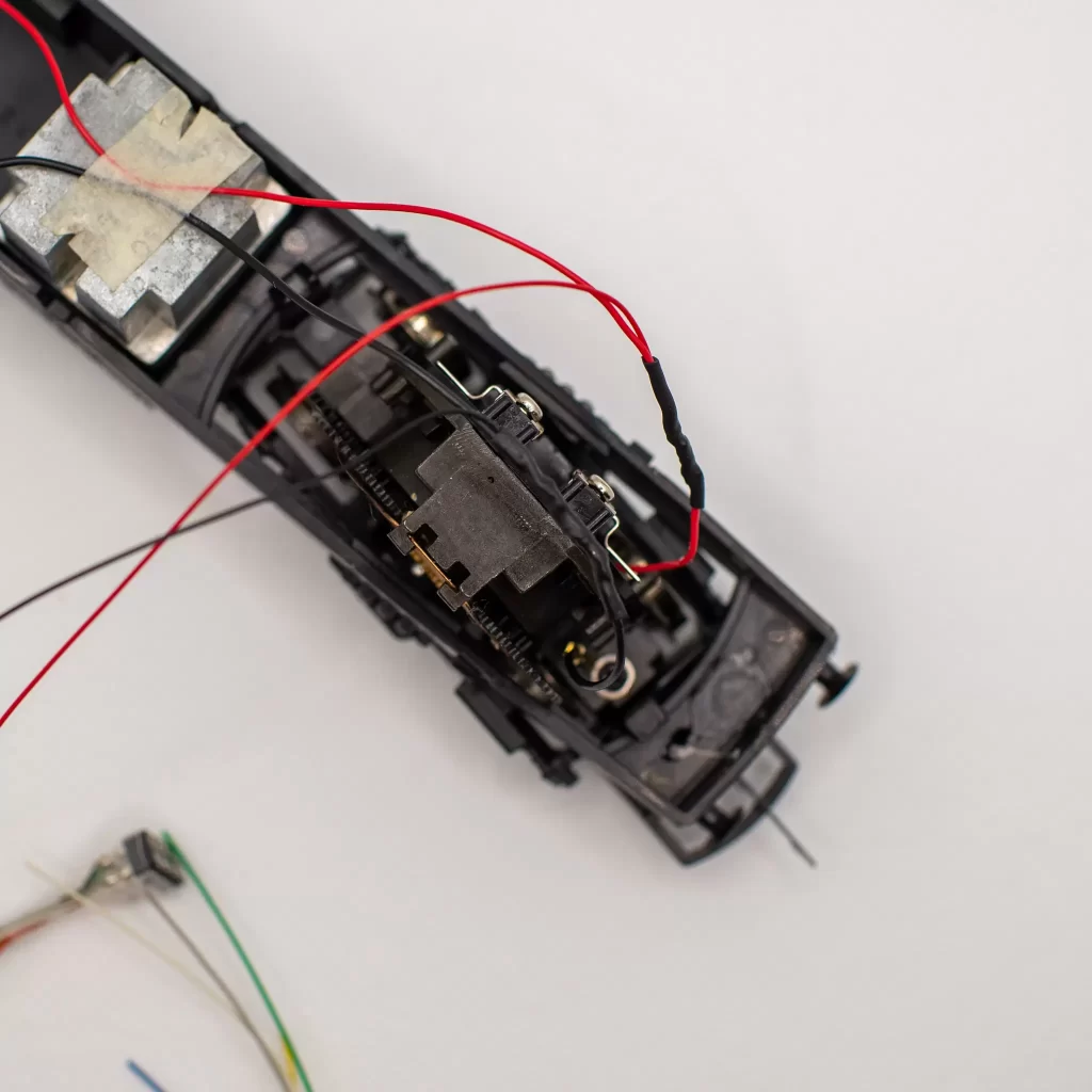
Step 4: Red to red and black to black
The two existing red wires form the Locomotive are now soldered together along with the red lead from the 8 Pin Decoder socket. It’s important to insulate this joint once soldered to prevent accidental contact in the body causing a short. Either with electrical tape or in this case some heat shrink tube.
This is a personal choice, heat shrink is a much neater finish and there’s no sticky residue from tape – but it’s harder to undo as it melts to the plastic insulation of the wires.
Once complete you should have 3 red wires joined together, and separately 3 black wires also joined.
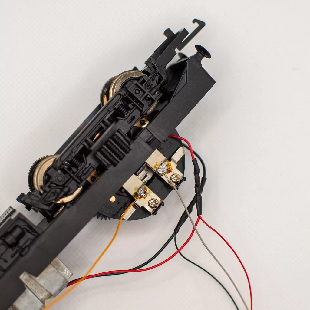
Step 5: Adding the DCC Decoder control lines
Now solder the orange and Grey wires to the motor where the capacitor was connected.
These wires are the ones that come from the decoder and provide power when the controller is set to drive this locomotive.
In this example Orange replaces the ‘Black’ connection and Grey replaces the ‘Red’ connection. It doesn’t matter hugely which way around you do these on a loco like this – it simply determines the direction ‘forwards’ becomes. If you’re now happy with which end is indicated as forwards or backwards on the controller you can just swap them over.
The rest of the wires from the decoder socket aren’t needed in this case. No lights or other DCC functions being installed (this time). I just bundled them together and secured them with some masking tape.
Step 6: Connect the DCC Decoder to the socket and secure in the chassis
There’s plenty of room in here and tons of space in the body too. For ease of opening up again I secured it to the chassis. I’ve used some masking tape to hold it down which shouldn’t leave and residue.
It’s important to make sure the existing red and black wires are run back in their existing paths. The red wire goes to the bogie and there’s a small channel in the rear assembly it needs to be pushed back into.
The black wires connect back to the switch in the roof of the body.
Step 7: Program the DCC Decoder and test
By default Hornby DCC decoders are set to ’03’. It’s a good test to change this number to make sure the DCC decoder can be read and written to, and then check the locomotive moves.
It took me about 15mins to do, including stopping to take the photos as I went. I’m very very pleased with this Class 86, especially now it’s had a DCC upgrade!
The Class 86 runs like a dream! Now onto the next one!